Noisy Cricket build guide
Posted on Fri 24 December 2021 in hardware
BOM
The BOM is also available on Octopart.
| Part | Count | Schema Ref | Description |
|---|---|---|---|
| ATMEGA32U4-MU | 1 | U1 | Micro controller |
| 1 kOhm Resistor | 1 | R5 | 0805/2012 |
| 0.1 uF Capacitor | 4 | C2, C4, C5, C6 | 0805/2012 |
| 1 uF Capacitor | 25 | C1, C3, C9-C31 | 0805/2012 |
| 22 Ohm Resitor | 2 | R3, R4 | 0805/2012 |
| 22 pF Capacitor | 2 | C7, C8 | 0603/1608 |
| 16MHz Crystal | 1 | Y1 | ABM8-16.000MHZ, 3.2mm x 2.5mm, 18 pF load capacity |
| 1N4148W | 24 | D1-D24 | Diode, SOD-123 |
| SK6812MINI-E | 23 | D25-D47 | RGB LED |
You should be able to get the parts from any electronics seller like Mouser, LCSC or Digikey.
You should be able to get some parts easier or cheaper on AliExpress, like these:
- SK6812 MINI-E RGB LEDs: aliexpress.com
- 1N4148 Diodes (SOD-123): aliexpress.com
Extra parts needed
- Alps EC11 or Bourns PEC11L compatible rotary encoder:
- Screws:
- ISO7380 M2x4mm: aliexpress.com
- ISO7380 M2x3mm: aliexpress.com
- M2x3+3 standoff: aliexpress.com
- DIN7991 M2x3 countersunk screws: aliexpress.com
- Threaded inserts
- M2x2 (OD 3.2mm): aliexpress.com
- USB 2.0 Type-C Connector Breakout Board:
- Pololu usb07b: pololu.com
- Rubber feet: aliexpress.com
Make sure to get the B type of the USB-C board. The A type is a bit longer and won’t fit.
Some parts like the hot swap sockets, switches, the knob and keycaps depend on your personal taste. The items in this list are the ones I picked. I would suggest to check at least the knob out for it’s size. There are a lot of knobs that don’t fit well or look weird because they are too small.
For Hot Swap sockets I used the Kailh CPG151101S11. They come in nice colors and work well. Switches for gaming should be linear with low travel, my favorites here are the TTC Titan Hearts RGB. They are very hard to come by if you haven’t ordered them when they came out (message me, I’ve got some spares). As keycaps I choose generic Cherry/OEM style milky keycaps. I don’t need the lettering on this small board and it let’s the RGB through very nicely. If you get keycaps with labels you might want to pick a profile like DSA where every key fits in every row. That makes it easier to find a set where the labels match your keys position. Lastly I used Durock v2 stabilizers. They come in nice colors and work really well. By now you can get the new Durock v3 variant, so I would recommend getting those instead. Makes sure to get the screw in PCB mounted variant and not the plate mounted ones. They should all fit the same holes in the PCB.
- Hot swap sockets:
- Black: aliexpress.com
- Colorful: aliexpress.com
- Switches:
- TTC Titan Heart: aliexpress.com
- Knob (17x16mm): aliexpress.com
- Milky keycaps (~20-25€):
- 2x 2U stabilizers (~5€):
Optional parts
If you’re into some more esoteric keyboard parts you can get these too. For better sound profile I would suggest to put some foam between the PCB and the plate. It absorbs a lot of unwanted noise. I like the keysporon more then the EVA foam, but try for yourself. The stickers for stabilizers and switches are definitely more on the esoteric site but they cost nearly nothing and if you’re getting foam and/or lube anyways, why not just get those too. Same as for the other foam, I like poron but you do you. I buy prelubed switches to avoid the hassle of doing those but get yourself some Krytox GPL 205g0 and lube your stabilizers. It really makes a difference for rattling noise and also smoothness. I usually skip switch films. Yes, this is where I draw the line for too esoteric stuff. But if you want you can open up your switches and add these too.
- Foam between PCB and plate:
- Stabilizer sticker:
- Switch sticker:
- Lubricant:
- Switch Films:
Building the PCB
You can get the Gerber files from Printables or GitLab. Send them to the PCB fab of your choice. I’ve got good results from JLCPCB (China) and Aisler (EU) or OSHPark (USA). Make sure to use Revision 2, as Revision 1 had some bugs you want to avoid.
Some PCB Fabs can even solder most components for you, but were is the fun in that. 😉
The rest is straight forward. Start with the crystal and the microcontroller, then continue with the smallest components and work your way up to the bigger ones. Make sure to put the LEDs in the correct direction. They shine through the hole in the PCB to the other site. Look at this picture to be sure.

As a help, use the interactive BOM file bom/ibom.html from the PCB repository.
You can mark what you’ve already done, so you don’t forget anything. Just open the file in a browser.
Also make sure to push down on the crystal so it makes a really good connection. I’ve had some boards where I couldn’t find out why they don’t work until I resoldered the crystal properly. They are very sensitive.
For the Crystal (Y1) and the microcontroller (U1) I recommend using a hot air gun. Put a good amount of flux on the
PCB, add some solder and preheat the PCB with 200°C. Then increase to 300°C - 400°C to solder it to the board. But don’t
blast it longer then half a minute or you could damage something.
If you’ve never done that before, try with some other components where you have spares. It’s good to get a feeling for when the solder melts before doing sensitive stuff.
Apart from the Microcontroller and the Crystal you should be able to solder everything else by hand with any regular soldering iron. Use the biggest solder tip you’re comfortable with. Make sure to have as much contact area as possible to make the heat transfer of your soldering iron as effective as possible. Usually it’s enough to heat up the area and the component you want to solder to for around 1s, then add the solder to it and heat for another second, then maybe another without adding solder to let it melt to all places it needs to be in. Adding more flux is always an easy way to success.
If you have any questions, feel free to reach out to me.
As the last steps for the PCB, screw in the stabilizers. Add stickers underneath them if you like. Also put some stickers underneath the metal bars if you want. Don’t forget to lubricate the stabilizers before you screw them in, if you want to do that.
Now is the time to put the foam on the PCB if you bought any. Put a switch in to check for correct alignment. It should be centered around the holes for the switches. It also can’t hurt to put some extra foam in the areas where there is still some space. Just cut the foam sticker to size.
Flashing the firmware
I’m trying to get this keyboard supported upstream in QMK. Once this is done, flashing firmware will be much easier with some web based tooling and GUI apps. For now you have to flash it manually from my QMK fork on the command line. This should work pretty much the same under Linux, macOS and Windows.
Once this keyboard is officially supported by QMK I’ll update the guide.
- Clone the firmware repository with git
-
Install the qmk CLI tool
-
Arch Linux:
pacman -S qmk -
macOS:
brew install qmk/qmk/qmk -
Windows:
- Install Python
- Install QMK CLI:
python -m pip install --user qmk
-
-
Change into firmware folder and check if everything works
cd qmk-firmware/ qmk --version qmk setup -
(Only for fresh ATMEGA chips) Erase microcontroller before flashing:
dfu-programmer atmega32u4 erase --force -
Compile the firmware with VIA support:
qmk compile -kb XenGi/noisy_cricket -km via -
Flash firmware:
qmk flash -kb noisy_cricket -km via -
Replug the keyboard back into your computer and try it out. Under Linux it should be detected in
dmesglike this:[855985.562865] usb 7-1.1.3: new full-speed USB device number 8 using xhci_hcd [855985.670542] usb 7-1.1.3: New USB device found, idVendor=4237, idProduct=1209, bcdDevice= 1.00 [855985.670547] usb 7-1.1.3: New USB device strings: Mfr=1, Product=2, SerialNumber=0 [855985.670549] usb 7-1.1.3: Product: Noisy Cricket [855985.670551] usb 7-1.1.3: Manufacturer: XenGi [855985.772162] input: XenGi Noisy Cricket as /devices/pci0000:00/0000:00:08.3/0000:c7:00.4/usb7/7-1/7-1.1/7-1.1.3/7-1.1.3:1.0/0003:4237:1209.0008/input/input55 [855985.866503] hid-generic 0003:4237:1209.0008: input,hidraw1: USB HID v1.11 Keyboard [XenGi Noisy Cricket] on usb-0000:c7:00.4-1.1.3/input0 [855985.872584] input: XenGi Noisy Cricket Mouse as /devices/pci0000:00/0000:00:08.3/0000:c7:00.4/usb7/7-1/7-1.1/7-1.1.3/7-1.1.3:1.1/0003:4237:1209.0009/input/input56 [855985.873117] input: XenGi Noisy Cricket System Control as /devices/pci0000:00/0000:00:08.3/0000:c7:00.4/usb7/7-1/7-1.1/7-1.1.3/7-1.1.3:1.1/0003:4237:1209.0009/input/input57 [855985.924250] input: XenGi Noisy Cricket Consumer Control as /devices/pci0000:00/0000:00:08.3/0000:c7:00.4/usb7/7-1/7-1.1/7-1.1.3/7-1.1.3:1.1/0003:4237:1209.0009/input/input58 [855985.924560] input: XenGi Noisy Cricket Keyboard as /devices/pci0000:00/0000:00:08.3/0000:c7:00.4/usb7/7-1/7-1.1/7-1.1.3/7-1.1.3:1.1/0003:4237:1209.0009/input/input59 [855985.977495] hid-generic 0003:4237:1209.0009: input,hidraw2: USB HID v1.11 Mouse [XenGi Noisy Cricket] on usb-0000:c7:00.4-1.1.3/input1
To change the layout you can use the VIA webtool.
If the keyboard isn’t detected right away during the flashing process, try pushing the RESET button on the back
before plugging it in. This should put it into BOOTLOADER mode.
If you struggle with something try to check the QMK docs or contact me.
Building the case
The files for the case can be downloaded from Printables. You can also find them in the CAD repository.
You will need three components, the upper case, lower case and the plate. There are two versions of the lower case depending on if you want to add an additional weight or not. The plate can be 3D printed or laser cut from metal or acrylic.
I ordered the additional weight and the plate made of brass from Laserboost. It’s very
cheap and good quality. Recently JLCCNC also started offering cheap CNC services but I haven’t tried them yet.
You can find the DXF files on [Printables][printables] or generate them from the
Git repository with OpenSCAD. Just use make dxf. You can also generate the
other files with make stl.
Upper case

For optimal quality print the upper case with as little layer height as possible. You can also use variable layer height. This makes the round edges look way better. I printed mine with Prusament PLA Galaxy Black and variable layer height on a Prusa MK4S and they came out really nice.
Lower case

The lower case can also be printed quite easily. If you decide to use the version with a weight, don’t forget to enable supports in your slicer. Printing orientation should be with the bottom down. The support for the weight can easily be removed and after adding the weight you won’t see the ugly side anymore.
Optional weight
Like I said, I ordered a brass weight from Laserboost and it made the whole build a lot nicer. Because of it’s small size, adding more weight makes a big difference when using the keyboard. The weight has a thickness of 1.5mm. You can use whatever material you like. It should have 4 counter sunk screws so it sits flush with the bottom. Mention that to Laserboost and they will drink proper holes for the counter sunk screws in it.
Plate
You could simply 3D print the plate but I would strongly suggest making it from acrylic or even metal. It really benefits from the better stiffness. Mine is made from brass and it also looks really nice. You can order a metal one from Laserboost or find a local hackspace or makespace that has a laser to make it out of acrylic.
Threaded inserts
There are also special tips to make this easier. CNCKitchen is selling nice ones but you can also use your normal soldering iron tip to put the threaded inserts in place. The specialised ones just make it a bit easier. You need to put 10 inserts in the lower case without a weight. 14 if you use the version with a weight. The upper case needs 4 more. They are all the same size - M2.
Make sure to only put threaded inserts in the outer corners of the upper case. The 4 inner holes are to make room for the screw heads from the lower case.
Putting it all together
The last build step is to prepare some wire to connect the USB-C breakout board to the main PCB. Double check the pin
descriptions and connect Data+, Data-, GND and 5V. The breakout board already has the correct resistors put in
place to act as a USB2.0 device. Now it’s just screwing things together.
Screw the USB-C breakout board into the lower case. Tug the cables neatly in the cable channel of the case, then screw in the PCB.
Next Put the plate in place and screw that in place. Now you can start putting switches in your PCB. Push them in gently, maybe you have to support the plate a little so the switches properly click into place.
Once they are all in, put your keycaps on. This is a good moment to try out if all switches work correctly. If they do, put on the top plate and screw it in from the bottom.
Now if you choose the additional weight, screw that in from the bottom and finish your build buy attaching some rubber feet.
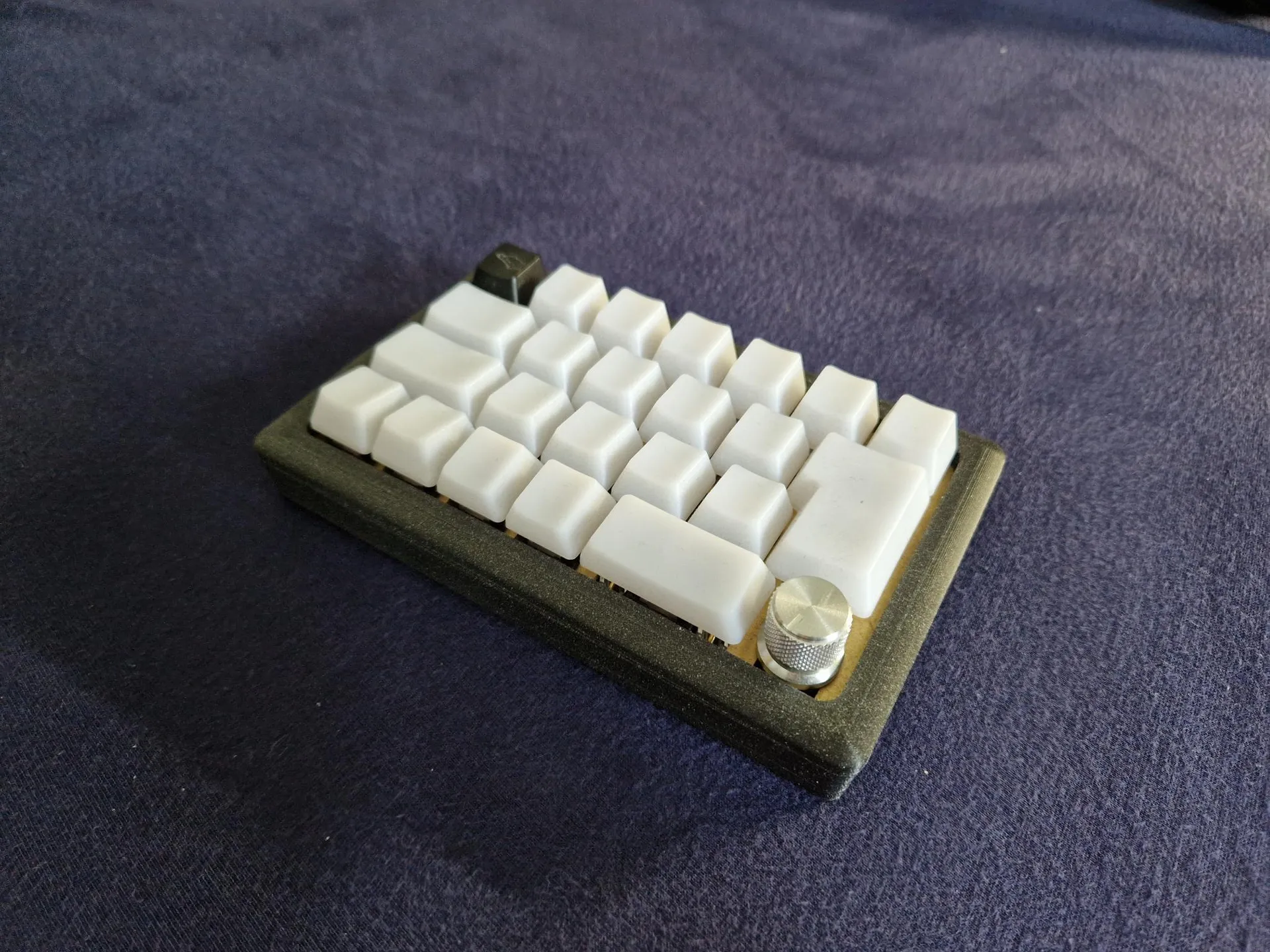
You’re done. Enjoy your new mechanical mini gaming keyboard and send me some pictures of the result.
Here’s a little gallery of the keyboard pictures I’ve got so far: